Fastened joints in the body-in-white, subframe, suspension and braking system endure vibration, impact and road-induced corrosion over the long term, while matching high-volume assembly at vehicle line rate.
Areas differ significantly in load mode, operating environment and failure consequences, so selection and process priorities also differ.
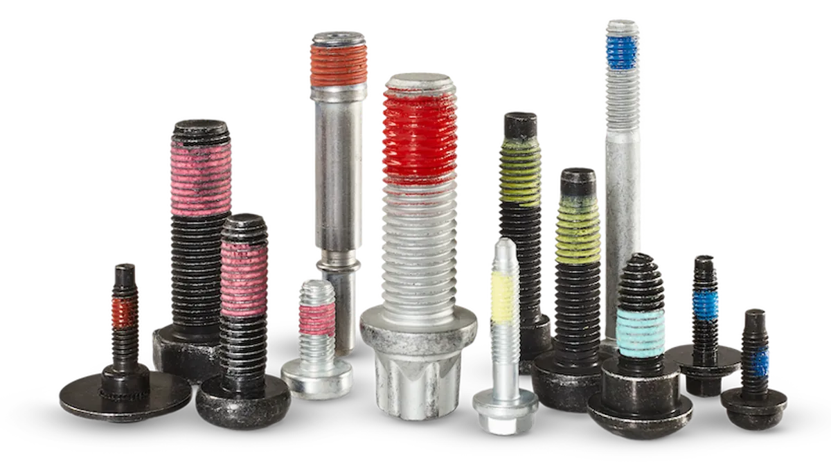
Grouped by joint type, each with a corresponding forming and surface treatment process route.
Used for subframe, suspension and braking system joints, mostly in flange or captive washer form, with property class determined by the loads at the joint.
Combined with bolts to form a complete joint; self-locking designs are used where anti-loosening is required, and self-clinching nuts for sheet-metal fixing points.
Used for sheet-metal and structural joints; threads are formed during assembly, eliminating the tapping operation and increasing joint strength.
The following are fastener types commonly used in this area, indicating the applicable product directions; for specific specifications and drawings, please submit them and an engineer will follow up.
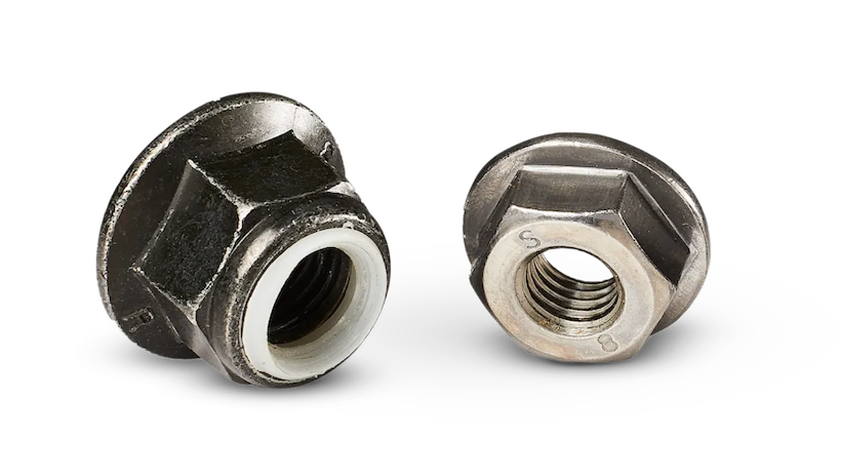
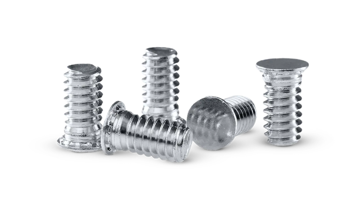
For an initial assessment of whether a requirement falls within the manufacturable range; specific solutions are subject to the drawing review conclusions.
| Item | Range and Notes |
|---|---|
| Joint Strength | Commonly class 8.8 and 10.9, determined by the calculated loads at the joint |
| Corrosion Protection Level | Zinc-nickel plating or Dacromet coating, selected to salt spray test requirements |
| Anti-Loosening Method | Pre-applied adhesive, self-locking design or captive washer, selected to serviceability requirements |
| Thread Size | Chassis joints commonly M6 – M14; drawings can be covered up to M2 – M18 |
| Sheet Thickness Suitability | Self-tapping and thread-forming types typically suit 0.8 – 3.0 mm sheet thickness |
| Delivery Support | Delivered by batch, with material certificates and inspection reports |
The following are the more common failure sources for this part category; they are identified and addressed before tooling.
Insufficient engaged threads directly reduce pull-out force; minimum engagement length must be calculated from sheet thickness and thread pitch.
Contact areas between aluminium parts and steel fasteners require isolation or a compatible coating.
Variation in friction coefficient significantly affects clamping force; lubrication and coating condition must be defined at the review stage.
Class 10.9 high-strength bolts, thread-forming screws, sealing plugs.
Self-tapping screws for plastics, headlamp adjustment mechanism parts, miniature fasteners.
Self-clinching studs and standoffs, anti-loosening pre-applied adhesive bolts, sealing plugs and earth studs.
Precision miniature screws, sheet-metal self-clinching nuts and standoffs, panel fasteners.
Provide drawings and operating condition requirements; DFM review conclusions and optimisation proposals delivered within 3–5 working days.
